 |
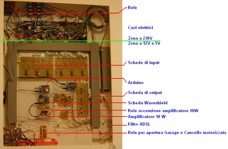
Domotic system in a box. |
 |
One moment the assembly of printed circuit boards on a plexiglass panel. |
 |
Photoresistor on the pins of the Arduino. Detects the ambient light to determine whether it is night or day |
 |
Modified switches with buttons and LED indicator. |
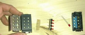 |
The parts needed to change the switches. |
 |
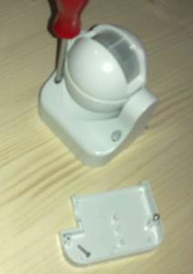
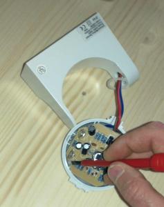
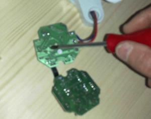
How to change the PIR step 0 |
 |
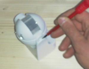
How to change the PIR step 1 |
 |
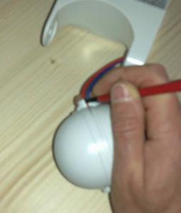
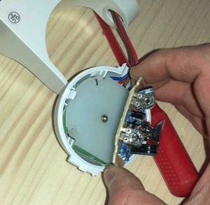
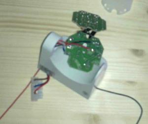
How to change the PIR step 2 |
 |
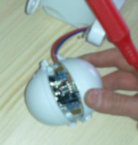
How to change the PIR step 3 |
 |
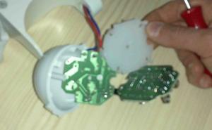
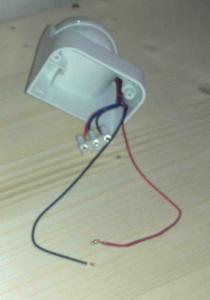
How to change the PIR step 4 |
 |
How to change the PIR step 5 |
 |
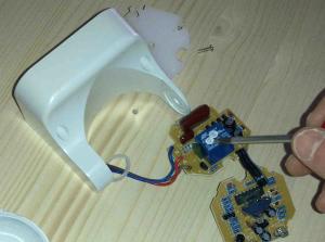
How to change the PIR step 6 |
 |
How to change the PIR step 7 |
 |
How to change the PIR step 8 |
 |
How to change the PIR step 9 |
 |
How to change the PIR step 10 |
 |
How to change the PIR step 11 |
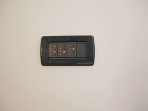 |
Buttons modified with LED indicator: photo 0 |
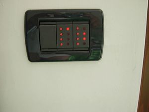 |
Buttons modified with LED indicator: photo 1 |
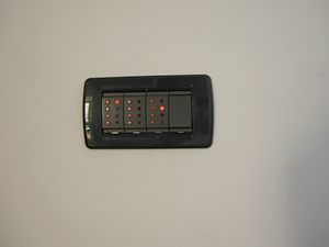 |
Buttons modified with LED indicator: photo 2 |
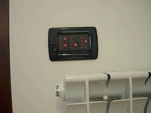 |
Buttons modified with LED indicator: photo 3 |
 |
The input Card with the MCP23016 Integrated Circuit. |
 |
The printed circuit to make the output card. |
 |
The output card with tree Arduino Atmega 328. |
 |
The waveshield card. |
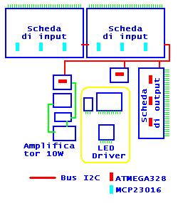 |
Domotic system schematics block with the IC ATMEGA328. |
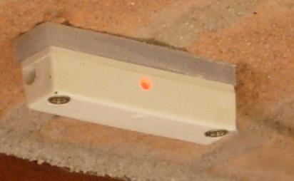 |
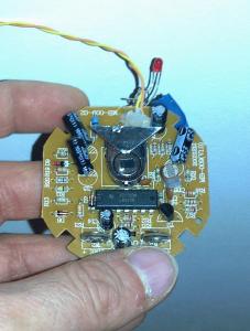
Reed Sensor with flashing led. |
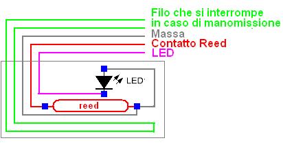 |
Reed Sensor: electric circuit. |
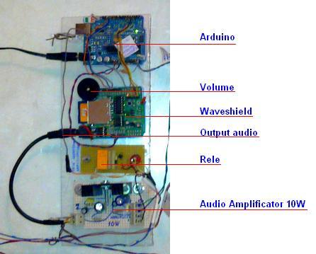 |
The set of circuits that control the sound - Arduino - Waveshield - 10W amplifier controlled by relay. |
| |
|
")
")