The history
The history
The first version of program was made with a cards that multiplexed input and output. This card must be connect to a PC’s parallel port. The PC would be cumbersome, but at that time (2003-2004), it was the method most economically for a program to communicate with the outside world.
As I proceeded to development boards, parallel Arduino (www.arduino.cc) project was born. Potential offered huge and cheap. It had everything we needed, in a tiny card. Became immediately clear that I had to to change direction, from a PC to this Arduino card.
So born the first version of the program and the first cards capable of multiplying available inputs and outputs to accommodate the needs of total control of a house.
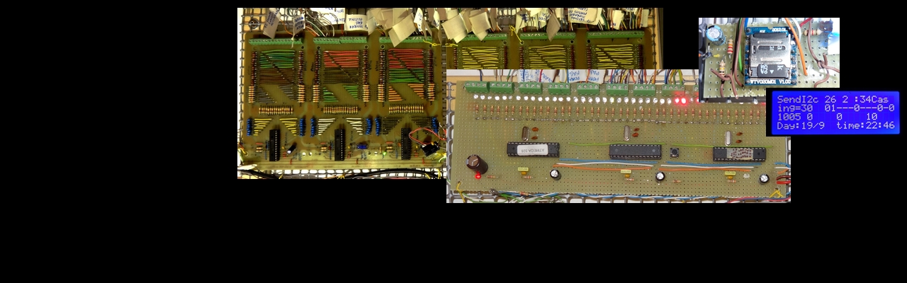
Input and output boards realized using two integrated common 8-Bit Shift Register: the 74HC595 and the 75HC165. But no one, other than in series, to detect 64 inputs and other 40 for output controll.
These boards have worked for more than a year, but have always had a minor defect; randomly, the sequence of bits that are converted from serial to parallel were altered by the spikes produced by the relay that themselves commanded.
It happened rarely, but when happened all the lights went on randomly for few hundred hundredths of seconds (time between two sending following the sequence of bits).
Although a minimum time was capable of being understood. Also relays’ that light up randomly are not suitable for automatic control systems such as the opening doors or irrigation systems.
The problem is typical of converters, serial / parallel and usually resolves with a small capacitor on the data lines of the integrated capacitor values, but all tested did not solve the problem.
I noticed from the analysis that the problem was present on the input detection circuit and also on the circuit output that controlling the relays’. But only the output was affected because the inputs were software filtered from the debounging routine (debounce).
The sequences of bits in input was controlled by the software while the sequences came to the integrated output. These, to them, did not have of any error correction mechanism based on redundancy of data.
So I have tried different methods to multiplex the inputs and outputs. The best it seemed to me to use the wire or I2C communication between integrated an standards introduced by Philips in the 80’s.
This standard allows ask the integrated the inputs that detect the state of their pin and then get a response. So I chose the integrated MCP23016 and I made a section repeated 6 times, to control 96 inputs. The maximum number of integrated MCP23016 that can be used together are 8. So I could only put two other integrated set as outputs for up to 32 pins. Since 32 outputs for controlling a house are a few I tried another solution without limits.
I decided to use the ATMEGA328, the same way as MCP23016, and then I created software that would make them similar and therefore with three inputs to select the address I2C from outside the integrated.
So these chips get instructions on what to do from the I2C bus and light up the pins. But a software can ‘do more’ and then I implemented in ATMEGA328 various routines for timing the ignition, the delay and flashes of each pin.
The Atmega328 so ‘packed in effect becomes an integrated circuit used in most home automation projects, timing, alarms and more.
(to complete)