Home automation system placement
The Arduino home automation system placement
When making a home automation is necessary to think about how to fix the hardware. The ideal would be a small closet or in my case build a box in a niche carved in the walls more. In this place will merge all the necessary cables, and small sensors but also those that control the electrical current various lights.
I chose not to use radio waves to determining the status of the sensors. This to not add wave to usual daily bombardment by radio, television and mobiles on the entire range of frequencies. Beyond what ‘also to avoid that ad-hoc equipment, disrupting communications, can making the system inefficient. However if you really can not be use wires, cards can be equipped with Arduino boards that communicate via radio waves.
In the solution described in this site Wire is also used for connecting sensors. This was possible because I have followed all the phases of the development of the house and then I passed a fair amount of corrugated pipes. If you have a house already built and there are no renovations, then it is more convenient to use the airwaves.
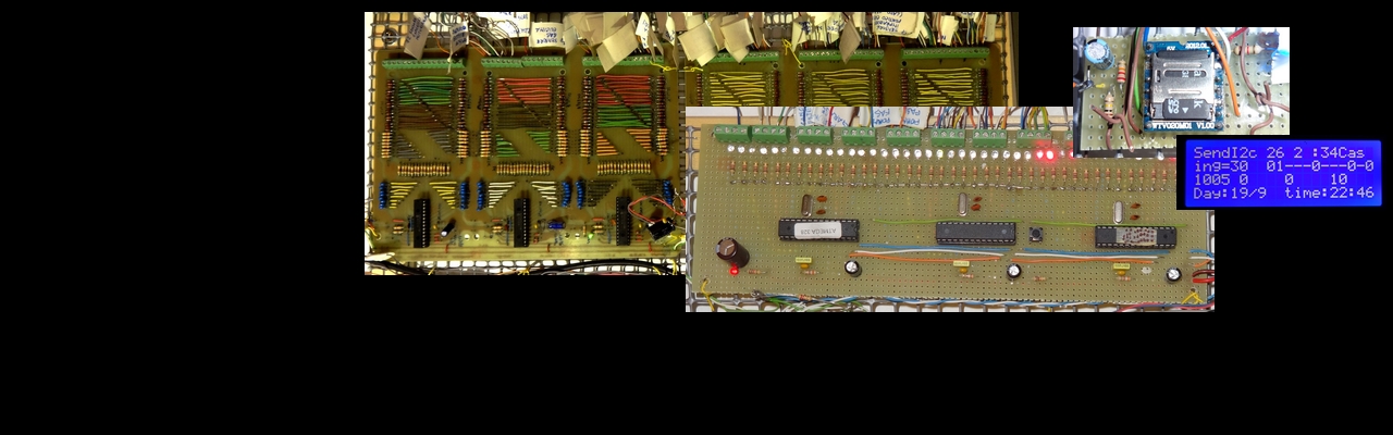
Returning to the site, all hardware is so centralized. It is also possible with a few changes Hardware distribute a sufficient number of boxes walled located throughout the house. In my case the construction is that you see in the picture. You immediately notice the green line that distinguishes the area 230v at the top from the low voltage 5V and 12V.
For electrical safety reasons, the areas at 230 is positioned at the top and is necessary a ladder to reach it. The low-voltage area is easily accessible.
All the wires are threaded into the guides gray willing to inverted U around the boards.
The boards are mounted on sheets of trasprente plexiglass wall mounted. This allowed to prepare and control boards in convenient place (a room equipped from laboratory) before you put them in the final location.
The power of the cards is provided by a small power supply that provides output voltages of 5V, 9V and 12V in addition to maintaining in office a battery capable of maintaining the system in operation for more ‘than 50 hours.
The power supply is on the lower left and not visible in the photo.
