Modify PIR sensor
How to change a PIR sensors to obtain an output to be connected to the home automation system or to a general alarm system.
A PIR alarm sensor has a significant cost, even 50 euros. A simple PIR sensor that only turns on the lights has a cost greatly limited. Electronics fairs can be found even at 7 euros.
From this premise, the idea of change a cheap sensor for equip it with an output suitable to operate the alarm systems.
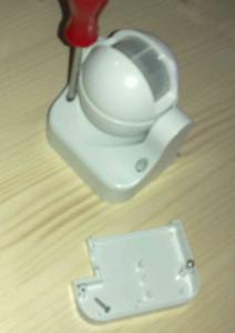 |
Remove the screws to free the base that attaches to the wall (see below). |
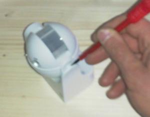 |
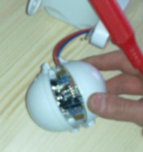
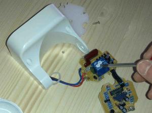
Remove the sensor from its mounting by inserting a screwdriver. |
 |
Open the sensor leveraging. Beware it is almost impossible to open it, without breaking the pins that hold it together and therefore in the process of reassembling the two parties must joined and sealed using silicone. |
 |
The opening… |
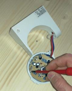 |
Disengage the PCB from the retaining clips. |
 |
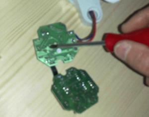
Unscrew the central screw that locks the plastic divider between the two printed circuit boards. |
 |
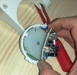
Remove the plastic. |
 |
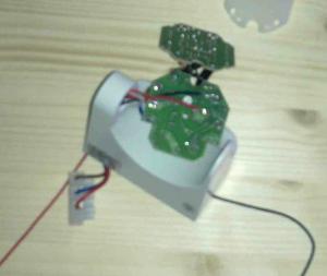
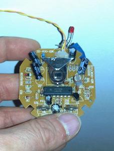
find the relays’ (pictured in blue). |
 |
Turn the circuit and find the contacts of the relays’. Taking great care, and do not work alone, you can power the circuit with the 230 and check the contacts of the relays with a tester. When the circuit detects a presence PIR, activates the relays giving its leaders a voltage of 22-24V, which you can read on the meter. It is a way to identify contacts and their polarity. Once found, you connect a red wire to the positive contact and a black wire to ground contact. Council to make all connections to the tester, before applying power the circuit with the 230v, in order to avoid touching the circuit board under tension. Do not feed the circuit if you are alone, and do not try to do everything described except if you have a experience in the electric field. If you decide to try the 230V power know that this is at your own risk. |
 |
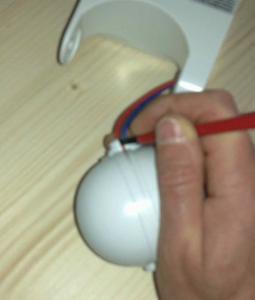
The red and black wires are welded to the ends of the relay. (Over time, the switch’s internal circuitry has evolved and diversified. The only constant is the relays which is easily identified and then used to make useful voltage to the head). |
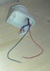 |
The sensor remounted. In series with the wires, you can now put a resistor of 1.2 K and a LED. You insert the LED into a piece of straw to drink, and on the other side, put a photoresistor. In this way, we have decoupled electrically the the sensor circuit across the resistor, which will connect the input to an alarm system. This small tube with inside the LED and the photoresistor, must be taped with electrical tape, electricians color black, to avoid the influence of ambient light. Do not connect these wires directly to the circuit, ie without LED and photo resistor coupled, because one of the two wires is connected directly to 230V and then, apart from being dangerous, it could destroy your alarm circuit. |
 |
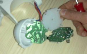
Finally a look at only the first circuit board of the sensor (in photos). This is reached by only three wires. Two for the 5V and the mass and the other goes to 5V as the PIR sensor is activated. In the picture, not visible, the third wire is connected to a 1k resistor and an LED for test. Mounting the sensor with only this circuit we got a sensor po |